NOTE: This is a working document that is regularly being edited and added to.
For many years the domain of high resolution mass spectrometry belonged to instruments with large magnets, namely magnetic sectors and FT-ICRs. While these instruments could provide very high mass resolution and accuracy, they were quite large and impractical for many labs due to the size of the magnets. After the turn of the century, a new contender named the "Orbitrap" rose to prominence. The Orbitrap utilizes electric fields to achieve high resolution mass analysis, eliminating the need for large magnets.
The Kingdon Trap
Electrostatic ion traps were used as early as the 1920's, usually with two coaxial electrodes: a cylindrical outer electrode and a thin wire center electrode. This geometry was pioneered by KH Kingdon, earning it the name "Kingdon Trap". If we assume that the electrodes are inifnitely long and a DC voltage is applied to the centeral wire, it creates an electric potential of the form:
$$\Phi = A\ln r + B$$
This hypothetical "radial logrithmic" field would allow for ions to orbit around the central electrode, assuming they had the appropriate starting conditions (kinetic energy and direction of motion). For example, a negative voltage on the central wire would allow a positive ion to orbit around it if the ion possessed the appropriate kinetic energy and direction of motion when first formed inside the trap. It may be helpful to think of the ions almost as planets orbiting around the sun, with the electric field from the central wire taking the place of the gravitational pull of the sun. Even though this radial potential would allow for orbiting motion, it does nothing to confine the ions in the axial direction. This was commonly achieved by applying a DC potential to endcaps with the same polarity as the ions (e.g. positive DC when trapping positive ions and vice versa). The introduction of the endcaps distorts the hypothetical potential of the infinite electrodes, but we won't consider that at this point. This video demonstrates an example of a positive ion that is orbiting around the central wire and oscillating back and forth axially:
The Knight Trap
While the Kingdon trap provided a way to confine ions for extended periods of time, it did not provide an effective way of discriminating between the m/z values of the trapped ions. In 1981, Knight published a paper in which the geometry of the outer electrode was modified in an attempt to make the electric potential have the form:
$$Φ = A \left(z^2 - \frac{r^2}{2} + B·\ln r\right)$$
The z2 portion of the potential causes ions within the trap to have harmonic motion in the z-direction (the center axis of the cylindrical symmetry), while the logrithmic portion of the potential causes the ions to orbit the central electrode:
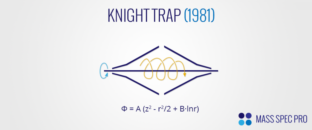
The frequency of ion motion in the z-axis is m/z-dependent, providing the possibility of discriminating between ions of various masses. However, Knight's trap was not perfect, in that it used simplified electrode shapes made of linear mesh segments instead of smooth, solid electrodes. These simplified electrodes did not provide the exact field that was desired, somewhat limiting the ability to discriminate between similar m/z values. Additionally, Knight did not focus on image current detection methodologies, instead opting to resonantly eject ions from the trap. The resonance ejection was accomplished by splitting the outer electrode into two halves and applying an RF waveform between them.
Despite the shortcomings of the Knight trap (e.g. its simplified geometry and lack of image current detection), the notion of mass-dependent harmonic motion along the central axis was fundamental to the future direction of the Orbitrap.
The Orbitrap
In 1999, a UK-based company named "HD Technologies" was issued a patent for a variation of the Knight trap geometry. The center and outer electrodes were given shapes that provided a potential of the form:
$$Φ = \frac{k}{2}\left((z-a)^2 - \frac{r^2}{2}\right) + B\ln \left(\frac{r}{c}\right) + d$$
This field is generally of the same form as the earlier "Knight" trap. However, the electrodes are not simplified in this case. Rather, they form the desired equipotential surfaces to truly generate the desired field:

As with the Knight trap, ions orbit around the central electrode and oscillate back and forth down the center axis with periodic motion:
The frequency of motion in the z-axis, ω, is given by:
$$\omega = \left(\frac{kz}{m}\right)^\frac{1}{2}$$
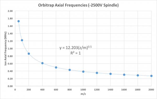
As is clear from the equation above, the frequency of ion motion is only a function of each ion's m/z value. If ions of the same m/z are introduced to the trapping field under tight temporal/spatial windows, they will oscillate back and forth along the z-axis together with a frequency that is dictated by their m/z value. This is clearly demsontrated by the simulation of ions in a trap with the spindle held at -2500V:
The motion in the x,y plane (viz. the "orbit" portion of the trajectory) is a different story, because it depends very strongly on the ion's initial conditions. Since the initial conditions can not be perfectly controlled, the ions do not move coherently in the x,y plane, quickly becoming randomized in these dimensions. The coherency of ion motion in the z-axis combined with the randomization of motion in the x,y dimensions results in packets of ions that resemble discs. These discs oscillate back and forth along the z-axis, with each disc having a specific axial frequency that is determined by the m/z value of its respective ion population.
Makarov's patent also explored methods of ion detection that could be employed with such a trap, focusing primarily on image current methodology. In short, the periodic motion of the ions along the z-axis could be detected as image current between the two halves of outer electrode. The following year (2000) an article in Analytical Chemistry more formally introduced the scientific community to the Orbitrap. This provided experimental proof of the new trap's high mass resolution, which was ~150,000 at the time.
Ion Injection
Injecting ions into the Orbitrap and having them form stable trajectories is a quite complex task, with strict requirements on space/time distributions and kinetic energy. In order for them to obtain stable orbits, ions' kinetic energy must be well matched to the voltage on the center electrode. If the kinetic energy is too low, the ions will be sucked into the center electrode. Conversely, if their kinetic energy is too high, ions will collide with the outer electrode. Ions should also be introduced in relatively tight time windows so that ions of any given m/z will oscillate along the z-axis in narrow bands, providing optimal signal-to-noise for the image current detection method. Although ions of the same m/z will oscillate with the same frequency along the z-axis, they will not oscillate coherently with each other if they enter the trap at different times. In an extreme case, ions could essentially cancel each other's image current out even though they were oscillating with the same frequency.
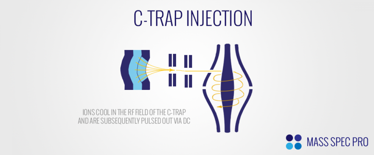
The tight requirements on kinetic energy and spatial/temporal spread have been addressed through the introduction of the so-called "C-Trap". The C-trap is essentially a "flatpole" ion guide that has both (a) a curved central axis and (b) a slot in the electrode closest to the Orbitrap. The trap is typically operated with ~1 mTorr of nitrogen, allowing very effective collisional cooling of ions in its RF field. Once the ions have accumulated/cooled sufficiently within the C-trap, the RF amplitude is quickly ramped down (in ~100-200 ns). The absence of an RF field means that the ions will no longer be confined radially within the trap's volume. Once the RF amplitude has dropped, the ions must be quickly pulled out of the trap so that they don't strike the trap electrodes. This is accomplished by appropriate DC potentials. For positive ions, the electrode furthest from the Orbitrap is the most positive, and the slotted electrode closest to the Orbitrap is the least positive. As a result, positive ions are pushed toward the Orbitrap, exiting the C-trap through its slotted electrode. They are subsequently accelerated/focused into the Orbitrap. Since the ions had very low kinetic energy within the C-trap, they have a narrow distribution of kinetic energies upon enetering the Orbitrap. Additionally, the rapid changes in RF and DC potentials that are used to empty the C-trap mean that the ions enter the Orbitrap in a narrow time window.
There is a delicate balance as ions are entering the Orbitrap's field. Ions are typically injected at a point that is offset from the center xy plane, closer to one of the narrow ends of the trap. They also enter the trap with trajectories that are tangential to the central axis. Por positive ions, a relatively large negative voltage is initially applied to the central electrode. The radial logarithmic portion of the field causes the ion trajectories to bend toward the central axis, beginning the "orbit" process. Additionally, the quadratic potential in the z-axis causes the ions to begin their axial oscillation. If the electric field remained fixed, ions would likely strike the outer electrode on the opposite end of the trap. In order to avoid this issue, the DC on the central electrode is ramped very quickly (tens of µs) to a more negative voltage, causing the electric field to change before the ions are able to travel to the other end of the trap. The larger negative voltage causes the axial component of ion motion to contract, preventing the ions from colliding with the outer electrode. The larger negative voltage also causes the radial motion of ions to contract, making them orbit with smaller radii. The use of a rapid DC ramp to allow effective ion injection/trapping is coined "electrodynamic squeezing".

This video shows the development of ion trajectories within the trap (from a side-on view) with and without electrodynamic squeezing. It is clear that the squeezing process quickly alters the radial and axial components of ion motion, minimizing the chances of ion losses on the outer electrodes:
Ion Detection
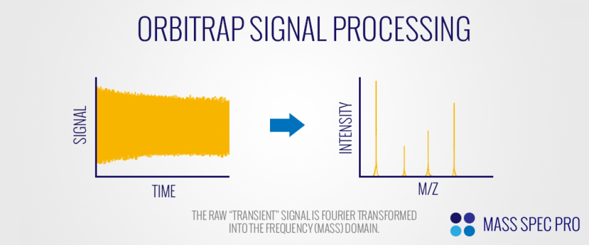
Ions inside the Orbitrap are detected via image current. As the ions oscillate back and forth in the harmonic axial potential they induce current on the outer electrodes. All of the ions inside the trap induce current on the electrodes simultaneously. As such, the raw image current (aka "transient) is a sum of many different sine waves in the time domain. In order to convert this signal to the desired mass spectrum, it is broken into its various frequencies via Fourier transform, providing a frequency spectrum. Since each distinct m/z value has a distinct axial frequency, the frequency spectrum is in effect a mass spectrum.
The induced image current is collected for some amount of time (tens to hundreds of milliseconds) with a relatively fast sampling frequency (e.g. 5 MHz). The sampling rate must be sufficiently high that it can reproduce the highest ion motional frequencies in the mass range of interest. The highest motional frequencies belong to the low m/z species. As such, the sampling rate of the image current will dictate the low end of the trap's detectable m/z range.
Since m/z and frequency are directly tied to each other, it is no surprise that mass resolution (m/∆m) is directly proportional to the frequency resolution:
$$\frac{m}{\Delta m} = \frac{\omega}{2\Delta\omega} = \frac{\left(\frac{kq}{m}\right)^\frac{1}{2}}{2\Delta\omega}$$
The best m/z resolution is attained at low m/z charge ratios and then decreases with the square root of the ion's m/z ratio. This is preferable in comparison to FT-ICR, for which frequency drops linearly with m/z. As such, the Orbitrap's m/z resolution does not decrease as quickly at high m/z. It should be noted that FT-ICR instruments have the ability to look at transients that are significantly longer than the Orbitrap's. When performing Fourier transform analysis, longer transients allow for finer discrimination between frequencies. For example, consider two sine waves with very similar (but different) frequencies. If you are only able to observe the two waves over a short time frame, it may be virtually impossible to tell them apart. However, if you are given more time to observe the waves, the frequency differences will become more obvious as they become visibly out of sync. This is precisely what happens when trying to resolve the axial motions of ions with very similar m/z values. Since their axial frequencies are extremely close to each other, it's difficult to tell them apart. However, if you observe the transient for increasingly longer times, it becomes easier to resolve them. Effectively, a longer transient analysis translates to a lower ∆ω value and therefore improved mass resolution. In other words, the longer the image current is collected, the higher the mass resolution. There is of course a tradeoff in this regard, because longer detection/analysis times will decrease the instrument's duty cycle.
So, if longer transient detection gives improved mass resolution, what dictates the longest possible transient length (and therefore maximal resolution)? Any process that causes imperfections in the ions' axial motions will gradually cause ions of the same m/z to lose their coherent motion with each other in the axial direction. This loss in coherency between the ions of a given m/z eventually means that their image currents start cancelling each other out and therefore no longer provide detectable signal. Numerous processes cause imperfections in axial motion. They include:
- imperfections in the trap electrodes that provide non-ideal fields
- inconsistency in the DC voltage that is applied to the center electrode
- space-charge repulsions between ions
- collisions with background gas molecules
Advancements in each area can improve m/z resolution and the maximum possible transient lengths. For example, more precisely machined/assembled electrodes and highly stable electronics can address issues #1 and #2. Space charge repulsions can be minimized by carefully controlling the number of ions in the trap by adjusting the injection conditions. Lastly, the number of collisions with background molecules can be minimized by pushing the vacuum chamber's pressure lower; in fact, Orbitrap instruments operate at ultrahigh vacuum to minimize this problem.
While the Orbitrap is known for its high mass resolution, it is also quite good in terms of mass accuracy. The same factors that distort ion trajections and mass resolution are the same issues that affect mass accuracy. Modern Orbitrap instruments have mass accuracies in the range of ~1-5 ppm. The combination of high mass resolution and high mass accuracy provides high fidelity chemical information to researchers.
Recent Developments
Even though the Orbitrap has provided a revolutionary way to perform high resolution mass analysis, researchers have continued to push its performance. One such advance has been the "High Field" Orbitrap. The geometry of the trap itself is modified, making the spindle electrode have a slightly smaller radius (5mm instead of 6mm) and the outer electrode radii are decreased even more (10mm instead of 15mm). These changes increase the electric field strength, which cause ion axial frequencies to increase. The higher frequences are easier to resolve for a given transient lengths, meaning that higher m/z resolutions can be achieved in the same amount of time with the "high field" trap.
Advancements have also been made in the detection process. A Fourier transform provides both phase and amplitude information for each frequency. However, most FT mass spectrometers have historically operated in a 'mangitude mode', combining the amplitude and phase values into a single 'magnitude' value. This has been done to keep peak shapes symmetric, but it comes at the expense of mass resolution by ~2x compared to the 'pure' spectrum. Thermo has recently utilized the 'Enhanced Fourier Transform (eFT)' process to take advantage of this improved resolution on its 'Orbitrap Elite' instruments.
The combination of high field traps and enhanced detection capabilities has demonstrated m/z resolutions in excess of 1,000,000. It appears that the Orbitrap is poised to become (and remain) the mass analyzer of choice for practical high resolution mass spectrometry for the foreseeable future.